In other words a weir is essentially a partial dam.
V notch water flow measurement.
Usbr 1997 suggests using the v notch weir equations for the following conditions.
Standard test method for open channel flow measurement of water with thin plate weirs nappe may cling to downstream weir face 90º v notch weir discharge table 2 5 accuracy channel floor 3 5 hmax hmax weir pool point of measurement.
Leakage measurement is one of the most important indicator of the overall performance of earth rock fill and concrete dams.
Leakage measurement is one of the most important indicator of the overall performance of earth rock fill and concrete dam.
The leakage rate is a function of the water level in the reservoir and depends either from the construction than the behaviour of the dam.
Water flow monitoring in open channels is widely employed in environmental and geotechnical field.
A weir as defined in the usbr measurement manual is simply an overflow structure built perpendicular to an open channel axis to measure the rate of flow of water.
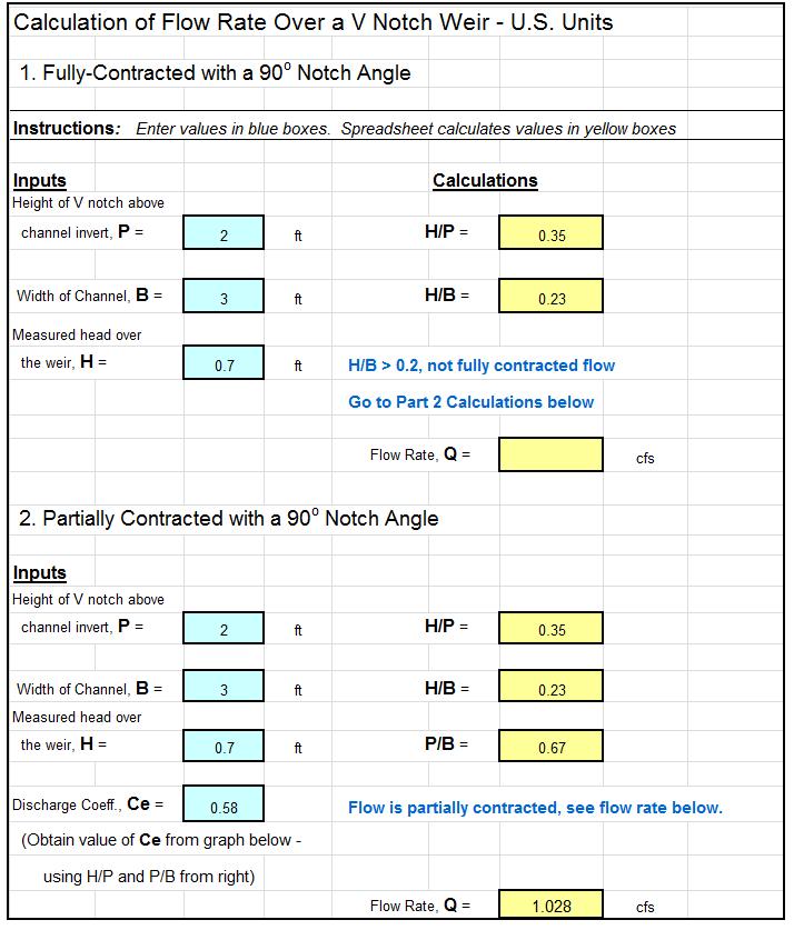
Q 8 15 c d 2 g 1 2 tan θ 2 h 5 2 2 where.
Qv qvml qvliv p252q water flow monitoring in open channels is widely employed in environmental and geotechnical field.
In order to allow the nappe body of water flowing over the weir crest to spring clear of the weir crest flow edge the crest should be no thicker than 3 mm 1 8 inch thick.
It is used to meter flow of water in the channel by measuring the head of water over the v notch crest.
For a triangular or v notch weir the flow rate can be expressed as.
It doesn t matter how thick the weir is except where water flows over the weir through the v the weir should be between 0 03 and 0 08 inches 0 8 to 2 mm thick in the v.
The triangular or v notch thin plate weir is an accurate flow measuring device particularly suited for small flows.
V notch and flow meters reference products codes.
The v notch weir is especially good for measuring a low flow rate because the flow area decreases rapidly as the head over the v notch gets small.
It works by raising the water level upstream of the weir and then forcing the water to spill over.
Sharp crested weir background.
Triangular or v notch weir.
Go to the left column then come down the left column till you reach 60 then across to the right to the 5 column your now at 60 5 65.
To find the flow rate through o.
Head h should be measured at a distance of at least 4h upstream of the weir.
Thicker than this the nappe may collapse against the downstream face of the weir due to insufficient aeration causing the weir to under indicate the actual flow rate.
Skrenter r instrumentation handbook water and wastewater treatment plants astm d 5242 92 2001.

